
3.2.3 Arrange

When clicking the "Top Toolbar - Arrange" button, the "Arrange" function bar will automatically pop up on the left side, which means the user has exited "One-Click" and selected to execute the workflow processing function instead.
Arrange mainly includes five sub-functions: "Optimize Orientation", "Auto Placement", "Abutment Scaling", "Auto Nesting", and "Model Connecting":
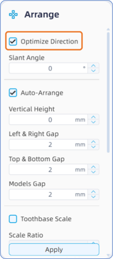
- Optimize Orientation: A checkable option. If this option is checked, the model's orientation will be automatically adjusted and placed according to the software's built-in placement logic; if unchecked, the model will be placed in its original imported orientation (without any orientation optimization).
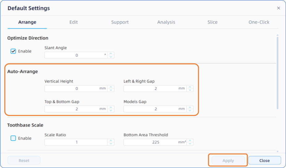
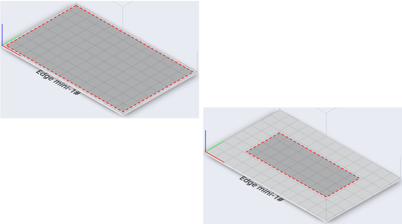
- Auto Placement: A default selection that cannot be unchecked. This parameter defines the placement height, boundary distance, and part spacing for the data files. Please note that the placement parameters configured here will only take effect for the current auto-placement execution. If you want the software to apply these parameters for all subsequent placements, they must be configured and applied in "Default Settings - Arrange - Auto Placement". At this time, the printable area of the platform will also change according to the boundary distance parameter settings (this indicator area will only change when adjusted in the default settings management interface; it will not change when parameters are input in the left function panel). Additionally, during the auto-placement process, if the current platform cannot accommodate all model files, the software will prompt whether to create a new platform for placement.
- Die Scaling: If this option is checked, the software will automatically identify parts that are smaller than the configured projected footprint area threshold (the default identification threshold is 225 mm² (15x15 mm)), and then scale the model along the XY axes according to the set scale factor coefficient. The default scale range is 0.9x to 1.1x.
- Auto Nesting: If this option is checked, the software will identify and group models based on the prefix of the file name, or classify them according to the part's projected footprint area. The former is mainly used for classifying multiple models within the same case, while the latter is primarily used for classifying supplementary abutments for printing. Once the auto nesting command is executed, multiple data files of the same category will be merged into a single grouped entity. This, in conjunction with the "Model Connecting" function, allows for the rapid connection and merging of print data.
- Model Connecting: The "Model Connecting" function will be activated and selectable only when the "Auto Nesting" option is checked. If this option is checked, models will be connected based on the auto nesting results. The parameters can be customized by the user, which mainly include the width, height, and insertion depth into the model of the connecting bar. Model connecting is primarily used for joining similar models during printing, which minimizes the difficulty of finding and classifying models during post-processing, especially for small-sized dies.